
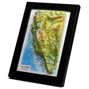

Raised relief maps offer a unique and intuitive way to visualize topography, bringing the contours of mountains, valleys, and plains literally to life under your fingertips. Unlike flat maps, which require interpreting lines and shading, a relief map provides an immediate, tactile understanding of the terrain's elevation changes. These maps are not just educational tools or decorative items; they are complex products resulting from a fascinating intersection of geography, data science, engineering, and manufacturing.
Have you ever wondered how that bumpy, three-dimensional representation of a landscape is actually made? It seems almost magical how detailed elevation data is translated into a physical, molded plastic sheet. The journey from digital elevation data to a finished, color-printed relief map is a multi-step process that relies on precise scientific principles and sophisticated technology.
This post delves deep into the science and techniques behind molding raised relief maps. We will explore the data sources used, the transformation of digital information into physical molds, the core molding process, and the intricate steps required to add geographical detail and finish the final product. By understanding the science behind this process, you gain a greater appreciation for these remarkable geographical tools.
Before we explore the manufacturing process, it is essential to understand what defines a raised relief map and why they hold such value. These maps are physical representations of terrain where the elevation is shown not just by contour lines, but by actual variations in the surface height of the map itself. This tactile dimension makes them particularly useful for educational purposes, planning, and conveying complex topographical information quickly.
A raised relief map translates the two-dimensional representation of horizontal location found on a standard map into a three-dimensional model that includes vertical dimension, or elevation. The height variations on the map surface are proportional to the actual changes in elevation on the Earth's surface, although vertical scale is often exaggerated to make subtle changes more noticeable. They are invaluable teaching aids, helping students grasp concepts like watersheds, mountain ranges, and plains in a tangible way.
Beyond education, relief maps are used in various professional fields. Geologists, hydrologists, hikers, and even military planners utilize them for visualization and analysis that is difficult to achieve with flat maps or even digital 3D models on a screen. Their ability to be touched and felt provides a different cognitive pathway for understanding spatial relationships and elevation.
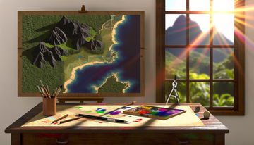
The desire to represent terrain in three dimensions is not new; it dates back centuries. Early relief maps were often handcrafted using materials like clay, plaster, or even carved wood. These early models were incredibly labor-intensive to create and were often unique pieces of art rather than mass-produced items.
Creating these historical maps required immense skill and knowledge of the terrain, often relying on field sketches, surveys, and an artist's interpretation. While impressive, they lacked the precision and scalability needed for widespread use. The advent of modern data collection and manufacturing techniques truly revolutionized the production of relief maps, making them more accurate and accessible.
The process of creating a modern molded relief map begins long before any plastic is heated or any mold is made. It starts with accurate data about the Earth's surface elevation. This data is the raw material that will eventually be transformed into the physical hills and valleys on the map.
Modern relief maps rely on sophisticated digital elevation data. The most common sources include Digital Elevation Models (DEMs), which are gridded arrays of elevation values representing the Earth's surface. These DEMs can be derived from various technologies.
One primary source is remote sensing, including satellite imagery and aerial photography combined with photogrammetry, which involves taking measurements from photographs. Stereo imaging from satellites like ASTER or terrain mapping missions like SRTM (Shuttle Radar Topography Mission) have provided global DEMs. Another increasingly important source is LiDAR (Light Detection and Ranging), a technology that uses pulsed laser light to measure distances to the Earth's surface, creating highly detailed and accurate elevation data points called point clouds.
Surveying techniques, both traditional ground surveys and modern GPS/GNSS measurements, also contribute to elevation data, especially for smaller, highly detailed areas. The accuracy and resolution of the final relief map are directly dependent on the quality and density of the input elevation data. Higher resolution data allows for the representation of finer topographical features.
Once the raw elevation data is collected, it needs to be processed and transformed into a format suitable for creating a three-dimensional model. This typically involves using Geographic Information Systems (GIS) and specialized 3D modeling software. The scattered data points or gridded values are used to create a continuous surface model.
In this digital environment, mapmakers define the geographic extent of the map and the desired level of detail. Crucially, they also determine the vertical exaggeration, which is almost always necessary. Without exaggeration, many subtle but important topographical features, like gentle slopes or small hills, would be imperceptible on a physical map at a practical horizontal scale. The software allows the designer to apply a multiplication factor to the elevation data, effectively stretching the vertical dimension relative to the horizontal.
The digital model is often visualized and refined at this stage, ensuring it accurately represents the intended topography and that the chosen vertical exaggeration effectively highlights key features without distorting the landscape beyond recognition. This digital 3D model serves as the blueprint for creating the physical mold.
With the precise digital 3D model complete, the next critical step is to translate this digital blueprint into a physical mold. This mold will be the tool used to shape the plastic sheet into the desired topographical form. The accuracy and durability of the mold are paramount to the quality of the final relief map.
Creating the mold begins with producing a physical master based on the digital 3D model. One common method involves using Computer Numerical Control (CNC) milling machines. The digital model is converted into toolpath instructions for the milling machine, which then precisely carves the positive form of the terrain out of a block of durable material, such as tooling board, metal, or dense foam.
Another increasingly popular method is large-format 3D printing. Specialized 3D printers can build up the master positive layer by layer using various polymers or composite materials. This method can be particularly good for capturing intricate details directly from the digital model. Both CNC milling and 3D printing require high precision to ensure the physical master accurately reflects the scaled and exaggerated topography defined in the digital model.
The resulting physical master is essentially a positive version of the relief map surface. From this master, the actual production mold is created. The choice between CNC milling and 3D printing, and the specific materials used, depends on factors like the required level of detail, the size of the map, the production volume, and budget.
The production mold, which will be used repeatedly in the molding process, needs to be durable and able to withstand the heat and pressure of molding hot plastic. Common materials for these production molds include epoxy resins, fiberglass, or even aluminum for very high-volume production runs. The process of creating the mold typically involves using the physical master as a pattern.
For epoxy or fiberglass molds, the master is prepared and a liquid molding material is carefully applied or cast over its surface. Once cured, this material forms a rigid negative impression of the master's topography – this is the production mold. For metal molds, the master might be used in a sand casting process or the mold might be directly CNC machined as a negative form.
The mold must be robust enough to maintain its shape under the forces of the molding process and capable of efficiently transferring temperature. Venting is also a critical consideration; small holes or channels must be incorporated into the mold design to allow air to escape during molding, ensuring the plastic is fully drawn into all the contours without trapping bubbles.
With the durable production mold ready, the stage is set for the main event: shaping the plastic sheet into the three-dimensional map. While several plastic forming techniques exist, vacuum forming is overwhelmingly the most common and effective method for creating raised relief maps.
The material used for the map itself is typically a thermoplastic sheet. Common choices include polystyrene, PVC (polyvinyl chloride), or ABS (acrylonitrile butadiene styrene). These materials are chosen for several key properties. They become pliable when heated, allowing them to be formed into complex shapes.
They also retain their shape once cooled, are relatively inexpensive, and can be easily printed upon. The thickness of the plastic sheet is selected based on the desired rigidity and scale of the final map; thicker sheets provide a more robust map, while thinner sheets might be used for smaller or less durable versions. The material needs to be consistent in thickness and composition to ensure uniform heating and forming.
Vacuum forming is a thermoforming process where a sheet of plastic is heated to a pliable temperature, then stretched over or into a mold, and finally forced against the mold by a vacuum. For raised relief maps, the heated plastic sheet is typically placed over the positive mold (the one with the hills sticking up).
Here is a simplified breakdown of the steps involved in vacuum forming a relief map:
The science behind vacuum forming relies on the principles of heat transfer and pressure. The uniform heating of the plastic is essential for consistent forming. The vacuum creates a pressure differential between the top and bottom of the sheet, harnessing atmospheric pressure (approximately 14.7 pounds per square inch at sea level) to exert a considerable force that pushes the softened plastic firmly into the mold's contours. Proper venting in the mold is critical to prevent air pockets from hindering the complete formation of the plastic against the mold surface.
While vacuum forming is dominant, other thermoforming techniques could potentially be used, though they are less common for typical relief maps. Pressure forming is similar to vacuum forming but uses positive air pressure on the top side of the plastic sheet in addition to or instead of a vacuum underneath, allowing for even greater detail capture and sharper features. Drape forming involves heating a sheet and simply draping it over a positive mold, relying mainly on gravity and the plastic's elasticity, suitable for simpler shapes.
Injection molding is another plastic process, but it is generally too complex and expensive for producing large, relatively thin relief map sheets with intricate, expansive topography. It is better suited for smaller, thicker plastic parts. For the scale and complexity of most relief maps, vacuum forming offers the best balance of cost-effectiveness, speed, and detail capture.
A molded plastic sheet, while showing the physical relief, is not yet a usable map. It needs geographical information – rivers, roads, boundaries, cities, and the all-important color that distinguishes different terrain types or elevations. This requires a complex printing and finishing process that aligns two-dimensional graphics with the three-dimensional surface.
One of the most ingenious aspects of modern relief map production is how the flat, two-dimensional map design is applied to the formed, three-dimensional surface. The map's graphical design (colors, labels, lines) is printed *before* the plastic sheet is molded. This might seem counter-intuitive, as stretching the plastic will distort the printed image.
However, sophisticated software is used to pre-distort the flat graphic design precisely opposite to how the plastic will stretch during the molding process. The software takes into account the specific mold shape, the type and thickness of the plastic, and the vacuum forming parameters to calculate exactly how much each part of the print needs to be stretched or compressed. The resulting pre-distorted graphic looks strange when viewed flat, but aligns perfectly with the geographical features on the plastic sheet *after* it has been vacuum formed.
Printing is typically done using large-format offset presses or digital printers capable of handling the plastic sheet material. UV-cured inks are often used for durability and vibrant color. After printing, the sheet is ready for the vacuum forming stage we discussed earlier. The accuracy of the pre-distortion calculation is crucial; any error will result in roads running off mountainsides or labels appearing in the wrong valleys.
After the printed and formed plastic sheet is trimmed, additional finishing steps are often performed to enhance durability and appearance. A common step is lamination. A clear, protective film is applied to the surface of the map, either before or after forming, depending on the specific process.
Applying the laminate *before* forming is common; the laminate is also pre-distorted and bonded to the plastic sheet before the sheet is heated and pulled into the mold. This protective layer guards the printed ink against abrasion, moisture, and UV fading, significantly extending the life of the map. The edges of the trimmed map are often finished, sometimes with a reinforcing strip or framing, to provide a clean look and prevent the edges of the plastic from being sharp or easily damaged.
Some manufacturers also add a backing layer, often cardboard or foam board, to the back of the molded plastic sheet. This backing provides rigidity and makes the map easier to handle and display. The combination of precise printing, accurate forming, and durable finishing results in the robust and informative relief maps we are familiar with.
Creating a raised relief map involves inherent trade-offs, particularly concerning scale and the faithful representation of the Earth's curvature and features. The most significant consideration is vertical exaggeration.
As mentioned earlier, vertical exaggeration is the practice of scaling the elevation dimension more drastically than the horizontal dimensions. This is done because, at typical map scales, the Earth's relief is surprisingly subtle compared to its horizontal extent. For example, Mount Everest, the highest point on Earth, is only about 8.8 kilometers (5.5 miles) high. If a map had a horizontal scale of 1:1,000,000 (where 1 cm on the map equals 10 km in reality), Mount Everest would only be less than 1 millimeter tall at that scale.
Such a small height difference would be practically invisible and certainly not tactile on a molded map. Therefore, the vertical scale is multiplied – often by a factor of 5, 10, or even more – relative to the horizontal scale. This makes hills and mountains appear much steeper than they are in reality but effectively highlights topographical variations that would otherwise be lost.
While necessary for readability and tactile feel, vertical exaggeration does introduce a distortion. It changes the apparent slopes and relative steepness of features. Map designers carefully choose the level of exaggeration based on the terrain being mapped and the intended use of the map, aiming for a balance between highlighting features and minimizing misleading visual impressions of slope angles.
Despite vertical exaggeration, maintaining the correct relative proportions of features is critical. The digital modeling and mold creation processes must ensure that the scaled heights of different peaks and the depths of valleys are accurately represented in relation to each other. The precision of the data, the fidelity of the digital model, and the accuracy of the mold fabrication all contribute to this.
The resolution of the input data and the capabilities of the molding process determine the level of detail that can be captured. Very fine features, like small gullies or subtle changes in slope on a large, regional map, might be generalized or lost due to the resolution limitations of the data, the mold, or the plastic sheet's ability to conform perfectly into every microscopic detail. Choosing the appropriate scale and level of detail for a relief map involves balancing the desire for accuracy with the practical limitations of the production process and the need for clarity for the user.
The unique tactile and visual nature of raised relief maps makes them valuable tools across a wide range of disciplines. Their ability to provide an intuitive understanding of terrain goes beyond what flat maps or even digital interfaces can easily convey to everyone.
In education, they are powerful teaching aids for geography, geology, environmental science, and earth science classes, allowing students to physically interact with the landscape. Hikers and outdoor enthusiasts use them for planning routes and understanding the challenges of different terrains. Emergency services and disaster relief planners can use them for visualizing areas impacted by floods, landslides, or other events where elevation is a critical factor.
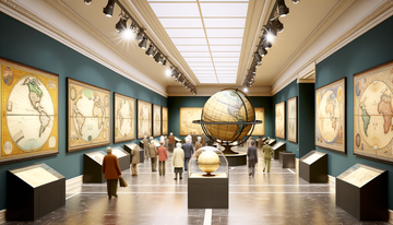
Urban planners, architects, and real estate developers might use them to understand site topography and its implications for development. Military strategists have historically used and continue to use relief maps for terrain analysis and planning operations. Furthermore, they serve as beautiful and informative display pieces in homes, offices, and museums, sparking curiosity about the world's landscapes.
While the process of molding raised relief maps is well-established, it comes with its own set of technical challenges. Achieving perfect alignment between the pre-distorted print and the formed plastic is one of the most significant hurdles.
Variations in plastic sheet thickness, heating inconsistencies, subtle differences in mold temperature, or fluctuations in vacuum pressure can all cause minor deviations in how the plastic forms, leading to misregistration of the printed image relative to the molded relief. Manufacturers employ strict process control and quality checks to minimize these errors.
Creating large, single-sheet relief maps also presents challenges in handling large sheets of hot, pliable plastic without introducing distortions or wrinkles. The cost of creating the highly accurate master positive and the durable production mold can also be substantial, especially for unique or custom maps. Balancing the desired level of detail with the limitations of the molding process and the need for a durable product requires careful engineering and material selection.
The science and technology behind raised relief maps continue to evolve. Advances in data collection, particularly from sources like high-resolution LiDAR and drone photogrammetry, provide increasingly detailed input for digital models. This allows for the creation of maps with finer features and greater accuracy than ever before.
Improvements in 3D printing technology are making it possible to create master positives more quickly and with higher resolution, potentially reducing the cost and time involved in mold making. Research into new plastic materials and thermoforming techniques could lead to more durable maps, materials that are easier to form, or even more sustainable options.
Furthermore, the integration of augmented reality or digital overlays onto physical relief maps is an exciting area of development. Imagine pointing your phone at a relief map and seeing digital information like historical battles, geological layers, or population density projected directly onto the physical terrain. This could combine the intuitive feel of a physical map with the dynamic information capabilities of digital technology.
The creation of a raised relief map is a sophisticated blend of art and science, transforming abstract digital elevation data into a tangible, three-dimensional representation of our world. It begins with precise data collection, moves through complex digital modeling and the meticulous crafting of physical molds, and culminates in the fascinating process of vacuum forming hot plastic onto these molds.
The ingenuity involved in pre-distorting printed graphics to align with the formed surface, and the careful consideration of factors like vertical exaggeration and material properties, are testaments to the technical expertise required. These maps bridge the gap between abstract geographical data and our innate human ability to understand the world through touch and sight simultaneously. They make the invisible contours of the land visible and tangible.
Whether used for education, planning, or simple fascination, raised relief maps provide a unique perspective on the Earth's surface. The science behind their creation ensures that these captivating representations are not only visually striking but also geographically accurate models that help us better understand the complex and beautiful topography of our planet.
```TestPlayNA: Your Memories, Elevated: National Park & Ski Maps.