

Maps have long served as essential tools for understanding our world, providing visual representations of geography that help us navigate, plan, and learn. While traditional 2D maps offer valuable information, they often struggle to convey the subtle nuances and dramatic variations of terrain with immediate impact.
This is where digital raised relief maps excel, transforming flat topographic data into compelling, three-dimensional visualizations that bring landscapes to life. For GIS professionals, cartographers, educators, and anyone seeking a deeper appreciation of Earth's surface, understanding the creation process of these visually stunning maps is incredibly valuable.
Creating an effective digital raised relief map is a sophisticated blend of data science, technical skill, and artistic sensibility. It involves multiple stages, each requiring careful attention to detail to accurately represent elevation and create a convincing illusion of depth and dimension on a two-dimensional surface.
This comprehensive guide will walk you through the intricate steps involved in producing high-quality digital raised relief maps. We will delve into data sources, essential processing techniques, various shading methods, and the strategies used to achieve that striking 'raised' effect, providing you with the knowledge to appreciate or even embark on creating these powerful cartographic products.
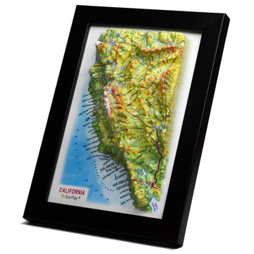
At their core, digital raised relief maps are two-dimensional or three-dimensional representations of terrain where elevation variations are depicted using shading, color, and sometimes simulated vertical exaggeration to create the *appearance* of a raised surface. Unlike physical relief models, these are digital files viewable on screens or printable on flat media, yet they convey topography with a vividness that flat contour lines alone often cannot match.
Their importance stems from their ability to quickly communicate complex terrain information in an intuitive way. They are invaluable for educational purposes, allowing students to easily grasp geographic concepts related to landforms.
In planning and engineering, they provide critical context for infrastructure projects, land use analysis, and environmental studies. For outdoor enthusiasts and recreational users, they offer visually rich maps that enhance route planning and understanding of challenging landscapes.
Effectively, digital raised relief maps bridge the gap between abstract data and visceral understanding, making topography accessible and engaging for a wide audience. Their creation process, while technical, is fundamentally about translating numerical elevation data into a visually compelling narrative of the land.
The cornerstone of any digital raised relief map is accurate elevation data. Without reliable information about the height of the land, any subsequent processing or visualization will be flawed.
The primary source for this information comes in the form of Digital Elevation Models (DEMs), which are raster datasets where each pixel's value represents the elevation at that specific geographic location.
DEMs are grids of elevation values and are the fundamental input for creating digital relief. The resolution of a DEM, meaning the real-world distance represented by each pixel, directly impacts the detail and accuracy of the final map.
Higher resolution DEMs, such as those derived from LiDAR (Light Detection and Ranging) surveys, can capture fine details like small hills, valleys, and even individual features, though they require significant processing power and storage. Lower resolution DEMs, like those from satellite missions such as SRTM (Shuttle Radar Topography Mission) or ASTER (Advanced Spaceborne Thermal Emission and Reflection Radiometer), cover vast areas but smooth out smaller features.
Choosing the appropriate DEM resolution is a critical first step, balancing the desired level of detail for the final map with data availability, processing capabilities, and the intended scale of the output. Often, multiple DEMs might need to be acquired and potentially merged to cover the entire area of interest at the desired resolution.
Once a DEM is acquired, it rarely arrives in a format perfectly suited for immediate use. Several crucial preparation steps are required to ensure the data is accurate, consistent, and ready for relief visualization.
These steps involve standard GIS operations but are particularly vital when dealing with elevation data where subtle errors can lead to noticeable artifacts in the final relief shading or 3D rendering.
The core data preparation tasks typically include:
DEMs, like all geospatial data, are referenced to a specific geographic coordinate system (GCS) and datum, and often stored in a projected coordinate system (PCS). Ensuring that all input data layers (DEM, potential boundary files, other geographic features) are in the same consistent coordinate system is fundamental. Reprojection might be necessary to match datasets or to work in a coordinate system appropriate for the study area and desired output projection.
If multiple DEMs of different resolutions are used, or if other raster data (like satellite imagery for texturing) needs to be combined with the DEM, resampling is required to make their pixel sizes match. Resampling can involve methods like nearest neighbor, bilinear interpolation, or cubic convolution, each affecting how new pixel values are calculated from the original data. Selecting the right method depends on the data type and the desired outcome, aiming to preserve data integrity while ensuring alignment.
Real-world elevation data is often imperfect. DEMs can contain spikes (unrealistically high values), wells (unrealistically low values), flat spots, or seams where different data tiles were joined. These artifacts can cause unsightly anomalies in relief shading. Cleaning involves identifying and correcting these errors using interpolation or other filtering techniques to create a smooth, continuous, and realistic surface model.
Completing these preparation steps meticulously is non-negotiable for achieving a high-quality digital raised relief map. A clean, correctly projected, and consistent DEM provides a robust foundation for all subsequent visualization techniques.
The magic of making a flat map appear three-dimensional primarily relies on relief shading, a technique that simulates how light and shadow would fall on the terrain if illuminated from a specific direction. This visual cue tricks the brain into perceiving height and depth on a 2D surface.
Relief shading is typically generated from the DEM using specialized algorithms within GIS or graphics software. The most common method is hillshading.
Hillshading calculates the illumination of each pixel based on the terrain's slope and aspect (the direction the slope faces) relative to a simulated light source. The light source is defined by two parameters: azimuth and altitude.
Azimuth is the horizontal direction of the light source, measured in degrees clockwise from North (0 degrees). A common choice is 315 degrees (Northwest), which casts shadows towards the southeast, a convention that often makes hills appear convex and valleys concave to the human eye, though this is a matter of cartographic convention and visual perception.
Altitude is the vertical angle of the light source above the horizon, ranging from 0 to 90 degrees. A lower altitude creates longer, more dramatic shadows, emphasizing subtle terrain features but potentially obscuring details in shadowed areas. A higher altitude results in shorter shadows and more uniform illumination, revealing detail everywhere but reducing the sense of depth.
The hillshading algorithm calculates the intensity of illumination for each pixel, typically outputting a grayscale raster where brighter pixels are facing towards the light source and darker pixels are in shadow. This grayscale image is then often used as an overlay, blended with other map layers.
While single-source hillshading is standard, more sophisticated techniques exist to enhance the perception of relief and overcome limitations, such as the loss of detail in deep shadows or on slopes parallel to the light direction. One such method is multi-directional hillshading.
Multi-directional hillshading combines hillshades generated from several different light source directions (e.g., from the Northeast, Northwest, Southeast, and Southwest). These different hillshade layers are then blended together, often weighted, to create a composite image that illuminates the terrain from multiple angles simultaneously. This technique reduces the problem of shadows obscuring detail and can produce a richer, more detailed representation of the terrain's texture and form.
Other advanced techniques involve varying the light source based on local topography or combining hillshading with other relief visualization methods like slope shading (coloring areas based on their steepness) or aspect shading (coloring areas based on the direction they face). These methods can be combined or used in conjunction with hillshading to produce highly detailed and informative relief visualizations.
While relief shading provides the primary visual cue for topography, incorporating other data layers significantly enhances the realism and usefulness of a digital raised relief map. These layers add geographic context and can be integrated in ways that respect the underlying relief.
Adding a surface texture on top of the shaded relief can dramatically improve the visual richness and realism of the map. The most common texture is an orthorectified satellite image or aerial photograph, which provides a realistic representation of the land cover, including forests, fields, urban areas, and water bodies.
This imagery is typically draped over the shaded relief. When done correctly, the shading should subtly influence the colors of the imagery, darkening areas in shadow and brightening illuminated areas, reinforcing the perception of three-dimensionality. Careful blending modes in graphics or GIS software are essential for achieving this effect naturally.
Alternatively, scanned historical maps, geological maps, or other thematic raster datasets can be used as textures, providing different types of information while still conveying the underlying terrain. The choice of texture depends entirely on the map's purpose and intended audience.
Essential geographic features such as rivers, lakes, roads, boundaries, and points of interest (often stored as vector data) must be added to provide context and navigability. Adding these features to a relief map requires careful consideration so they do not obscure the terrain representation.
Linear features like rivers and roads need to appear as though they follow the terrain. In advanced 3D rendering, this happens naturally. In 2D representations incorporating shading, symbology might need adjustments, such as using subtle lines or adding minimal halos, to ensure they are visible against the varied background without flattening the perceived relief.
Area features like lakes or parks also need to be integrated. Water bodies are typically shown with uniform color or texture and should ideally appear flat or conform to the appropriate water level in the 3D visualization. Raster data, such as land cover classifications, can also be overlaid, often with transparency applied so the underlying relief remains visible.
The integration of these diverse data types is a delicate balance. The goal is to create a visually harmonious map where the relief is prominent but other essential geographic information is clearly presented and easily legible.
The term "raised relief" implies a vertical dimension, and while shading creates the illusion in 2D, true digital raised relief often involves rendering or simulating a third dimension. This is where the DEM is used not just for shading, but as a literal height source.
Earth's topography, especially on regional or global scales, is relatively flat compared to its horizontal extent. Mountains that appear towering on a map are mere wrinkles on the planet's surface. To make subtle terrain variations visible and dramatic on a map, vertical exaggeration is almost always necessary.
Vertical exaggeration involves scaling the elevation values upwards relative to the horizontal scale. For example, a 5x vertical exaggeration means that every meter of actual elevation is depicted as 5 meters on the vertical axis of the visualization. The amount of exaggeration depends on the map scale, the variability of the terrain, and the desired visual effect.
Too little exaggeration might make the terrain look flat, while too much can distort slopes and make features appear unnaturally steep or spiky. Determining the optimal vertical exaggeration is a design decision that greatly influences the final appearance and interpretability of the map.
There are several approaches to converting the DEM and associated layers into a visualization that truly represents or simulates raised topography.
Many modern GIS software packages (like ArcGIS Pro, QGIS, Global Mapper) and specialized 3D modeling software (like Blender, Cinema 4D) have built-in capabilities to create 3D scenes directly from DEMs. The DEM is used to create a surface model, onto which imagery, hillshading, and vector data can be draped. The user can then adjust the viewpoint, lighting, and vertical exaggeration before rendering a 2D image or even an interactive 3D model. This method allows for highly realistic views from any angle.
Even when the final output is a flat 2D image, techniques from graphics software can simulate a "raised" look beyond simple shading. The DEM can be used as a displacement map or bump map in rendering software. A displacement map literally pushes the vertices of a flat 2D plane upwards based on the elevation value, creating true 3D geometry. A bump map doesn't alter geometry but modifies surface normals to simulate bumps and indentations under lighting, giving the *appearance* of texture and height. These techniques, especially displacement mapping, can produce highly detailed relief renderings even for static 2D maps.
The choice between these techniques depends on the required output (static image vs. interactive 3D), the level of realism desired, and the software and skills available. Software-based 3D views are common for standard cartographic products, while displacement mapping might be used for more artistic or hyper-realistic visualizations.
With the core relief visualization complete and other geographic features integrated, the final stages involve refining the map's appearance, adding essential cartographic elements, and composing the layout.
While grayscale hillshading is effective, adding color based on elevation can greatly enhance the map's readability and aesthetic appeal. Hypsometric tinting involves assigning a color ramp to different elevation ranges. For instance, green might represent lower elevations, yellows and browns mid-elevations, and white or purple high elevations. This adds another layer of information and helps viewers quickly discern elevation zones.
When combining hypsometric tints with hillshading, the color ramp is typically overlaid with the shaded relief, often using transparency or specific blending modes (like multiply or overlay in graphics software) so that the shading still affects the perceived brightness and texture within each color zone. Careful selection of color ramps is crucial; they should be intuitive, colorblind-friendly, and aesthetically pleasing.
A map is incomplete without labels, a legend, a scale bar, a north arrow, and potentially a title and source information. Adding these elements to a relief map presents unique challenges.
Placing labels on varied terrain requires sophisticated labeling engines that can position text intelligently to avoid steep slopes, follow curves (like rivers or roads), and remain legible against the background. Techniques include using halos or outlines around text, placing labels in flat 'collars' or boxes, or dynamically adjusting font size and placement based on the underlying relief.
The legend must clearly explain all symbology used, including hypsometric tints, feature types, and potentially the vertical exaggeration factor. The scale bar and north arrow provide orientation. The title should be descriptive, and source information is essential for data provenance.
The overall composition involves arranging all these elements into a coherent and visually balanced layout. This stage is where the map transitions from a data visualization into a finished cartographic product ready for its intended use.
Digital raised relief maps are not merely visually appealing; they serve practical purposes across numerous fields. Their ability to immediately convey topographic complexity makes them invaluable tools.
In education, they make geography lessons tangible and engaging. For land management and environmental science, they aid in understanding drainage patterns, identifying suitable building sites, and analyzing ecological zones.
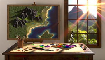
In the realm of art and visualization, they are used to create stunning landscapes for films, games, and illustrations. For outdoor recreation and navigation, they provide unparalleled insight into trail difficulty and route finding.
The impact of these maps lies in their ability to democratize the understanding of complex terrain. They make it easier for non-experts to grasp the lay of the land and make informed decisions or simply appreciate the beauty of Earth's varied surface.
The creation of digital raised relief maps is a multi-step process that synthesizes technical skills in GIS and graphics software with cartographic design principles. It begins with acquiring and meticulously preparing accurate elevation data, primarily DEMs.
The process then moves into the art of visualization, using techniques like hillshading and multi-directional shading to simulate the effects of light and shadow on the terrain. Integrating surface textures and other geographic features adds realism and context, transforming the shaded relief into a rich geographic depiction.
Achieving the compelling 'raised' effect involves careful consideration of vertical exaggeration and utilizing 3D rendering or displacement mapping techniques to give the visualization depth. Finally, adding conventional map elements like color ramps, labels, and a legend refines the product, making it a complete and informative map.
Mastering this process requires patience, attention to detail, and a willingness to experiment with different data sources, parameters, and blending techniques. The result, however, is a powerful and beautiful cartographic product that offers unique insight into the physical world.
Digital raised relief maps stand as a testament to the power of modern mapping technology to visualize complex data in ways that are both scientifically accurate and aesthetically captivating, bringing the dimensionality of our planet to our screens and printouts.
```TestPlayNA: Your Memories, Elevated: National Park & Ski Maps.