Okay, here is an authoritative, SEO-friendly blog post based on the presumed Topic 2: The Process of Making Raised Relief Maps, following your requirements and constraints.
***
**Meta Title:** From Data to Display: The Step-by-Step Process of Crafting Raised Relief Maps
#
Crafting Landscapes: The Comprehensive Process of Making Raised Relief Maps
Introduction: Unveiling the Art and Science Behind Topographic Masterpieces
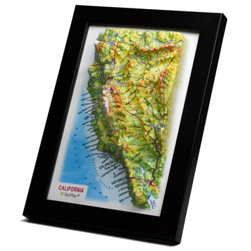
For centuries, maps have served as indispensable tools, guiding exploration, facilitating understanding, and capturing the imagination. While flat maps provide essential geographic information, there's a unique magic inherent in a raised relief map. These tactile landscapes allow us to literally feel the contours of the Earth, offering an intuitive grasp of topography that a two-dimensional representation simply cannot replicate.
Yet, despite their striking visual and tactile appeal, the intricate process of transforming abstract elevation data into a tangible, three-dimensional landscape remains a mystery to many. How do mountains rise from a flat sheet of plastic? How is precise geographic detail maintained throughout the transition from digital file to physical form? This blog post aims to demystify that fascinating journey.
We will embark on a detailed exploration of the step-by-step process involved in crafting modern raised relief maps. From the initial acquisition of complex geospatial data to the final finishing touches, we will uncover the blend of traditional cartographic principles and cutting-edge technology that makes these maps possible. Whether you are a geography enthusiast, an educator, a designer, or simply curious about the making of these remarkable objects, this guide offers a comprehensive solution to understanding their creation. We will cover key stages including data acquisition, digital design and modeling, the critical thermoforming process, and the final assembly and finishing.
Section 1: The Foundation - Data Acquisition and Preparation
Every raised relief map, whether depicting a small national park or an entire continent, begins its life not in a workshop, but as a vast collection of numerical data points. These points represent elevation and other geographic features across the chosen area. The accuracy and resolution of this initial data are paramount, directly influencing the fidelity and detail of the final physical map. Without precise foundational data, even the most sophisticated manufacturing processes cannot create an accurate representation of the landscape.
The Blueprint of Reality: Gathering Topographic Data
The primary ingredient for a raised relief map is topographic data, which describes the shape and height of the Earth's surface. Over the past few decades, the availability and resolution of this data have dramatically increased thanks to advancements in satellite technology, aerial surveying, and remote sensing. The most common format for representing this data for relief mapping is the Digital Elevation Model, or DEM. A DEM is essentially a grid of numbers where each cell corresponds to a specific location on the ground and the number represents its elevation above a reference point, such as sea level.
Several sources contribute to creating these vital digital blueprints. Satellite missions like the Shuttle Radar Topography Mission (SRTM) or the Advanced Spaceborne Thermal Emission and Reflection Radiometer (ASTER) have provided near-global DEM coverage at various resolutions. Airborne surveys using technologies like Lidar (Light Detection and Ranging) offer extremely high-resolution data, capable of capturing fine details of the terrain, vegetation, and even man-made structures. Additionally, traditional ground surveys and digitized contour lines from existing paper maps can still be used, although they are often more labor-intensive and may lack the uniformity and resolution of modern digital methods. Choosing the appropriate data source depends heavily on the required scale, detail, and geographic coverage of the intended map.
Understanding Data Formats and Structures
Topographic data comes in various digital formats, each suited for different types of geographic information system (GIS) software and processing workflows. Raster data, like DEMs, organizes data into a grid of cells or pixels, where each cell holds a specific value (e.g., elevation). This format is ideal for representing continuous surfaces such as terrain. Vector data, on the other hand, represents geographic features as points, lines, and polygons, defined by coordinate pairs. Features like rivers, roads, political boundaries, and place names are typically represented as vector data.
For creating a raised relief map, the raster DEM is the critical layer that defines the three-dimensional form, while vector data provides the cultural and hydrological context that will be printed onto the surface. Both data types must be properly managed and integrated within a GIS environment. Understanding the spatial reference system (projection and datum) of each dataset is crucial to ensure that all layers align correctly, preventing geographical inaccuracies in the final map. Inconsistent spatial referencing is a common hurdle that must be meticulously addressed during the data preparation phase.
Data Cleaning and Validation
Raw topographic data is rarely perfect and often contains errors, anomalies, or inconsistencies that must be addressed before it can be used to generate a relief map. These issues can range from small spikes or depressions caused by sensor noise to larger voids or gaps where data could not be collected. Data cleaning involves identifying and correcting these errors using various interpolation, smoothing, and filtering techniques within GIS software. For instance, gaps in a DEM might be filled by estimating elevation values based on surrounding valid data points.
Validation is another crucial step, ensuring that the processed data accurately reflects the real-world terrain. This might involve comparing the DEM against known ground control points, cross-referencing with other elevation data sources, or visually inspecting shaded relief models derived from the data. A clean, validated, and accurate DEM is the absolute cornerstone upon which the entire physical map is built. Any errors introduced at this initial stage will be permanently imprinted onto the physical surface of the relief map, undermining its accuracy and utility. This phase requires patience, attention to detail, and a strong understanding of geospatial data properties.
Section 2: Designing the Landscape - Digital Modeling and Design
Once the raw topographic data has been acquired, cleaned, and validated, the next phase involves transforming this digital information into a design file ready for physical production. This stage is where cartographic design principles meet digital modeling techniques, shaping not just the physical form but also the visual information that will be overlaid onto the three-dimensional surface. It requires skilled designers who understand both the geographic realities and the capabilities and limitations of the manufacturing process. The design phase is arguably where much of the artistry of modern relief mapmaking resides.
Sculpting the Digital Terrain: Software and Design Principles
Specialized software is essential for manipulating and preparing the geospatial data for relief map production. GIS software like ArcGIS or QGIS is used for initial data processing, spatial analysis, and integrating various data layers (elevation, roads, rivers, boundaries, labels). However, dedicated 3D modeling or terrain visualization software is often employed to fine-tune the digital elevation model and prepare it for creating the physical mold or print file. These programs allow for detailed manipulation of the terrain surface, previewing the 3D result, and optimizing the model for the subsequent manufacturing steps.
Key design principles come into play here. Choosing appropriate color schemes and symbology for the printed map layers ensures that geographic features are clear and easy to interpret. Text placement must be carefully considered so that labels are legible when printed onto a three-dimensional surface. Visual hierarchy guides the viewer's eye, highlighting important features while providing necessary context. The design must anticipate how the flat print will distort when formed into a 3D shape and compensate for this distortion. This requires careful registration and potentially pre-distorting the printed image.
Vertical Exaggeration: Giving Mountains Their Due
One of the most critical design decisions in relief mapmaking is determining the degree of vertical exaggeration. While mathematically accurate, rendering topography using a 1:1 vertical scale (meaning the vertical height is scaled identically to the horizontal distance) often results in very subtle, almost imperceptible relief, especially for areas with gentle slopes or limited elevation range. To make the terrain features visually apparent and tactile, the vertical scale is typically exaggerated relative to the horizontal scale. This means that mountains will appear taller and valleys deeper than they are in reality, relative to their horizontal extent.
The amount of exaggeration is a subjective choice, ranging from 2x to 20x or even more, depending on the landscape being depicted and the desired effect. Too little exaggeration can make the relief difficult to discern, while too much can distort the landscape and potentially mislead the viewer about the true steepness of slopes. Skilled mapmakers carefully balance visibility and perceptual accuracy, often choosing an exaggeration factor that best highlights the characteristic landforms of the region. The chosen vertical scale directly impacts the height of the final formed plastic and must be accounted for in the mold design and manufacturing process.
Adding Thematic Data and Preparing the Print File
Beyond the bare topographic surface, relief maps typically include a wealth of additional geographic information – rivers, lakes, coastlines, roads, cities, political boundaries, parks, and place names. This thematic data is usually prepared as separate layers in vector or raster format and then overlaid onto the shaded relief representation of the terrain. Color ramps are applied to the elevation data to create hypsometric tints, which visually represent elevation zones using different colors. Shaded relief, generated by simulating illumination from a virtual light source, is often added to enhance the perception of terrain shape.
All these layers – hypsometry, shaded relief, vector features, labels – are combined into a single, high-resolution image file. This image file will be the graphic layer printed onto the flat plastic sheet *before* it is thermoformed into its three-dimensional shape. This is a crucial step, as the print must align perfectly with the underlying relief form. Complex software algorithms are used to take the 3D model and 'unfold' it back into a 2D representation that, when formed, will precisely match the underlying topography. This 'unfolding' process accounts for the stretching and distortion that occurs during thermoforming, ensuring that printed features like rivers follow the valleys and mountain peaks are accurately labeled. The final output of this design phase is typically a large, high-resolution print file (e.g., TIFF, GeoTIFF) that includes all the visual information needed for the map surface, along with a separate file defining the 3D shape (often a heightmap or a mesh model).
Section 3: Bringing it to Life - Printing and Thermoforming
This stage is perhaps the most visually dramatic part of the process, where the flat, two-dimensional design and the abstract digital elevation model are physically transformed into a tangible, three-dimensional object. It involves printing the carefully designed graphic onto a special type of plastic sheet and then using heat and vacuum to mold that sheet over a form representing the landscape. This fusion of print and form requires precision machinery and careful control of environmental conditions. The success of the final map hinges significantly on the execution of this step.
Printing the Base Map
The meticulously designed and distortion-corrected graphic file is printed onto a flat sheet of plastic. The type of printing process used depends on the scale of production and the desired quality. Offset printing is often used for large production runs, offering high resolution and vibrant colors. Digital printing, particularly using UV-cured inks, is increasingly common for shorter runs or custom maps, offering flexibility and faster setup times. UV inks are particularly well-suited as they cure instantly under ultraviolet light, are durable, and can adhere well to the types of plastic used in thermoforming.
The plastic substrate is typically a thin sheet of materials like PVC (Polyvinyl Chloride), ABS (Acrylonitrile Butadiene Styrene), or styrene. The thickness and type of plastic are chosen based on the desired durability, flexibility, and how well it retains shape after forming. The ink used must be flexible enough to stretch and distort along with the plastic during the thermoforming process without cracking or losing its vibrancy. The printed sheet must also be precisely registered, often with fiducial marks, to ensure correct alignment with the mold in the next step. Any misalignment here will result in the printed features not matching the underlying physical terrain.
Selecting the Right Materials
The choice of plastic material is critical for the quality and longevity of the raised relief map. Common materials include:
* Polystyrene: Economical and easy to form, often used for educational or promotional maps.
* PVC (Polyvinyl Chloride): Durable, flexible, and takes ink well. A popular choice for many commercial maps.
* ABS (Acrylonitrile Butadiene Styrene): Very durable and impact-resistant, suitable for maps that will see heavy use.
The plastic sheet needs to be uniform in thickness and free of defects. Its thermal properties are also important, as it needs to soften predictably when heated and retain its formed shape when cooled. The print applied to the plastic must also be compatible with the material and the thermoforming process, ensuring it doesn't crack, smudge, or peel during heating and stretching. The interaction between the ink, the plastic, and the heat applied is a key factor in achieving a high-quality result.
The Thermoforming Process: Heat, Vacuum, and Form
Thermoforming is the core manufacturing technique that gives raised relief maps their shape. It involves heating a flat sheet of plastic until it becomes pliable, and then using a vacuum or pressure to force the plastic against a three-dimensional mold.
The Mold: The Physical Representation of the Terrain
The mold is the physical form that the heated plastic sheet will take the shape of. Molds can be created in several ways. Traditionally, they were hand-sculpted or carved from materials like plaster, wood, or resin based on topographic contours. Modern methods increasingly rely on computer-aided manufacturing (CAM), where the digital elevation model is used to machine a mold from materials like aluminum, epoxy tooling board, or even dense foam using CNC (Computer Numerical Control) milling machines. Molds can be either positive (representing the mountains and valleys as raised features) or negative (representing the landscape as depressions and peaks). The choice of mold type and material impacts the complexity and cost of the process. A precisely machined mold is essential for transferring the subtle details of the digital model to the physical plastic.
The Thermoforming Machine
The thermoforming machine typically consists of a heating element, a clamping system to hold the plastic sheet, a mold table, and a vacuum system. The printed plastic sheet is secured in the clamping frame above the mold. The heating element, often consisting of ceramic or infrared heaters, then heats the plastic evenly to its forming temperature, which varies depending on the type of plastic used. As the plastic softens, it becomes flexible and malleable.
The Vacuum and Forming
Once the plastic reaches the optimal temperature, the mold table is typically raised or lowered into position beneath the plastic sheet. A vacuum is then applied through small holes in the mold, drawing the soft plastic down tightly onto the mold's surface. The atmospheric pressure on the upper side of the sheet combined with the vacuum below forces the plastic to conform precisely to the shape of the mold. The printed ink on the plastic stretches and distorts during this process, which is why the original graphic design had to be pre-corrected for this distortion. The timing, temperature, and vacuum pressure are all critical variables that must be precisely controlled to ensure an accurate and bubble-free form. Incorrect settings can lead to thin spots, tearing, poor detail transfer, or inaccurate shape.
The Cooling Process
After the plastic has been pulled onto the mold, it must be allowed to cool and solidify while still held under vacuum or pressure. Rapid, even cooling is important to minimize shrinkage and distortion and to help the plastic retain the fine details of the mold. Fans or cooling systems are often used to accelerate this process. Once sufficiently cooled and rigid, the vacuum is released, and the formed plastic sheet, now a three-dimensional relief, is removed from the mold. The result is a single sheet of plastic with the landscape physically raised and the geographic information printed onto its surface.
Section 4: The Finishing Touches - Trimming and Assembly
With the thermoforming complete, the basic raised relief form is created, but it is not yet a finished map ready for display. The formed plastic sheet will have excess material around the edges from the clamping process, and it typically needs to be mounted and framed to become a durable and aesthetically pleasing final product. This stage involves trimming away the waste material and assembling the formed plastic sheet onto a backing board, often adding a frame for protection and presentation. These steps require careful handling to avoid damaging the formed surface.
Refining the Landscape: Trimming, Finishing, and Framing
The first step in finishing is trimming the excess plastic material from around the formed map area. This waste material, sometimes called flashing, is a necessary byproduct of the thermoforming process, providing the area for the clamping frame to hold the sheet. Trimming is typically done using precision cutting tools, such as die cutters or CNC routers, to ensure clean edges and the correct final dimensions of the map. Accuracy is important to ensure the map fits correctly into its intended backing or frame. Manual trimming might be used for low-volume production or irregular shapes, but it is more labor-intensive.
Mounting and Assembly
Once trimmed, the formed plastic relief needs structural support to prevent it from flexing or potentially cracking, and to provide a surface for hanging or display. This is achieved by mounting the formed plastic sheet onto a rigid backing board. Materials like foam core, hardboard, or corrugated plastic are commonly used for backing. Adhesive is applied to the backing board or the back of the formed plastic, and the two are carefully brought together, ensuring precise alignment. Rolling or pressing the surface gently helps to ensure good adhesion across the entire area, including into the depressions of the relief.
For added durability and aesthetic appeal, the mounted relief map is often placed within a frame. Frames can range from simple metal or wood borders to more elaborate display cases, protecting the edges and giving the map a finished look. Sometimes, a protective coating or laminate is applied to the printed surface *before* forming, or less commonly *after* forming, to protect the ink from scratches, UV fading, and moisture, although post-forming lamination is challenging due to the 3D surface. Quality control checks are performed throughout these steps to ensure the map is free of defects, the print is aligned, and the assembly is secure.
Adding Protective Coatings (Optional)
As mentioned, adding a protective layer can enhance the durability of the map. This is usually a clear, flexible coating or laminate applied to the printed plastic sheet before the thermoforming step. This pre-coating stretches along with the plastic and ink during forming, providing a protective barrier against physical wear and environmental factors like sunlight. While adding a step and cost to the process, it significantly extends the lifespan and usability of the map, especially for those intended for public display or frequent handling in educational settings. The coating must be carefully selected to ensure it is compatible with the plastic and the ink, and that it does not yellow over time or negatively impact the visual clarity of the map.
Section 5: Variations and Advanced Techniques
While thermoforming over a printed sheet is the most common method for mass-producing raised relief maps, other techniques exist, particularly for smaller, highly detailed, or custom models. These methods often involve different manufacturing processes and materials but share the same goal of translating digital topographic data into a physical, three-dimensional form. Exploring these variations highlights the evolving nature of cartographic production and the increasing accessibility of digital fabrication technologies. Each technique offers distinct advantages and is suited for different applications, scales, and budget levels.
Beyond the Standard: Alternative Methods and Innovations
The traditional thermoforming process, while effective for producing many identical maps from a single mold, can be expensive for creating unique or very large-scale custom pieces. This has led to the development and adoption of alternative methods, often leveraging advancements in 3D printing and CNC machining. These techniques can sometimes offer greater detail or allow for more complex forms than traditional thermoforming, although they may also have limitations in terms of material choices, scale, and production speed compared to high-volume thermoforming. The choice of method depends heavily on the specific requirements of the project.
3D Printing for Relief Models
Additive manufacturing, commonly known as 3D printing, offers a direct way to create three-dimensional topographic models. Using techniques like Fused Deposition Modeling (FDM), Stereolithography (SLA), or Selective Laser Sintering (SLS), a 3D printer can build a relief model layer by layer directly from a digital terrain file. This method is excellent for creating small-scale models, prototypes, or highly detailed representations of specific areas. It allows for virtually unlimited geometric complexity and custom designs without the need for expensive molds.
The main limitation of 3D printing for larger maps is often the build volume of the printer and the time and cost associated with printing large areas. Post-processing, such as painting or applying graphics, is also different than with thermoforming, as the color and labels are not typically printed simultaneously with the form. Color can be applied afterwards through painting, airbrushing, or applying printed overlays, which requires careful registration to the 3D surface. Despite these challenges, 3D printing is a powerful tool for creating custom, high-detail relief models, particularly for educational demonstrations or artistic applications.
CNC Milling for Molds or Direct Models
CNC (Computer Numerical Control) milling uses computer-guided cutting tools to shape material based on a digital design. As mentioned earlier, CNC milling is widely used to create the molds for the thermoforming process, offering high precision and durability. However, CNC milling can also be used to directly carve a relief model from a block of material such as foam, wood, or plastic. This is particularly effective for creating large-scale, durable relief models, such as those seen in museums or visitor centers.
Direct milling from a block of material eliminates the need for the thermoforming step, but it can generate significant material waste in the form of shavings and dust. Similar to 3D printing, applying detailed graphics to a CNC-milled relief typically requires post-processing steps like painting, airbrushing, or applying carefully cut and registered printed overlays. The level of detail achievable depends on the milling tool size and the material being cut. CNC milling is a versatile technique, useful both for creating the tools for other processes and for producing final relief models directly.
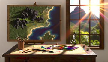
Hand Sculpting (Traditional Methods)
Before the advent of digital data and automated manufacturing, relief maps were often created through painstaking hand sculpting. Mapmakers would use topographic contours and cross-sections to guide the building up or carving away of materials like plaster, clay, or papier-mâché on a baseboard. This was a highly skilled craft, requiring significant artistic talent and a deep understanding of topography.
While not used for mass production today, hand sculpting is still practiced for artistic relief maps or historical reproductions. It allows for a level of artistic interpretation and texture that can be challenging to replicate with purely automated methods. The process is slow and labor-intensive, with the finished relief being painted and labeled by hand. This traditional method highlights the historical roots of relief mapmaking as a blend of scientific representation and artistic interpretation.
Adding Lighting or Other Features
Modern relief maps can incorporate additional features to enhance their utility and visual appeal. This might include integrated LED lighting to simulate sun angles and create dynamic shaded relief effects, highlighting different aspects of the topography. Interactive elements, such as embedded sensors or touch-sensitive areas linked to digital displays, can provide additional information about specific locations on the map. These advanced features merge physical cartography with digital technology, creating educational tools or display pieces that are both informative and engaging. Such additions require careful planning during the design phase and integration during the assembly stage, adding complexity to the manufacturing process.
Conclusion: Bridging the Gap Between Data and Discovery
The creation of a raised relief map is a fascinating journey that seamlessly blends the precision of geospatial science with the tangible craft of manufacturing. From the initial collection of vast datasets capturing the Earth's surface to the intricate dance of printing, heating, and forming plastic over a precisely shaped mold, each step requires specialized knowledge and careful execution. The process transforms abstract numbers into a physical, intuitive representation of our world, allowing us to touch mountains and trace valleys with our fingertips.
Whether produced through high-volume thermoforming or crafted as a unique piece using 3D printing or CNC milling, the resulting raised relief map serves as a powerful tool for education, visualization, and appreciation of topography. They offer a unique perspective that complements traditional flat maps and digital displays, providing a concrete understanding of landforms that is difficult to achieve through other mediums. The next time you encounter a raised relief map, take a moment to consider the complex interplay of data, design, and manufacturing that was required to bring that landscape to life. It is a testament to human ingenuity and our enduring desire to understand and represent the world around us in ever more compelling ways.
This detailed exploration of the crafting process reveals not just a manufacturing pipeline, but a sophisticated system that translates the invisible structure of terrain into a visible, tactile, and understandable form. Raised relief maps are more than just objects; they are bridges between complex data and intuitive discovery, allowing us to connect with geography on a truly physical level.
***